Tuesday, May 31, 2011

DVI Part 2

So, thanks to JBerg's most helpful and correct comments in my previous post, I indeed had my wiring all messed up. Because the pinouts are created using the female plugs, when you're wiring to a male plug, you have to line it up with the pinout from the back. I had no idea.

Pinout for 17" iMac G4 Screen to DVI
So I started fresh, Unsoldering all the wires from the DVI cable and soldered them back into their correct spaces. I also took some time to create a hopefully very intuitive pinout for the model of screen I had (using the info JBerg gathered)

After it was all said and done, SUCCESS!!! My backlights still aren't hooked up, but as you can see, the picture is coming through crystal clearly! This is very exciting

Wednesday, May 25, 2011

DVI Part One

Once the new screen arrived, I got right to work on DVI solder prep. To start, I removed the shrink wrap holding the two video wires together and used a pocket knife blade to carefully fold back and remove the thin metal housing.

Then I used the same blade to pry up the plastic tabs on the connector and free the little golden cable ends.

Because the DVI Cable is so large in comparison to the hole at the top of the iMac's dome, it's necessary to feed the neck wires into the dome and reattach it to the neck. If you use the two black screws, you won't have to use the white plastic cap that will force each of the four wires off in a different direction and shorten the amount of cable you have to work with. Just make sure you skip one screw hole so you can fit the white plastic cap back over the top when you're done.

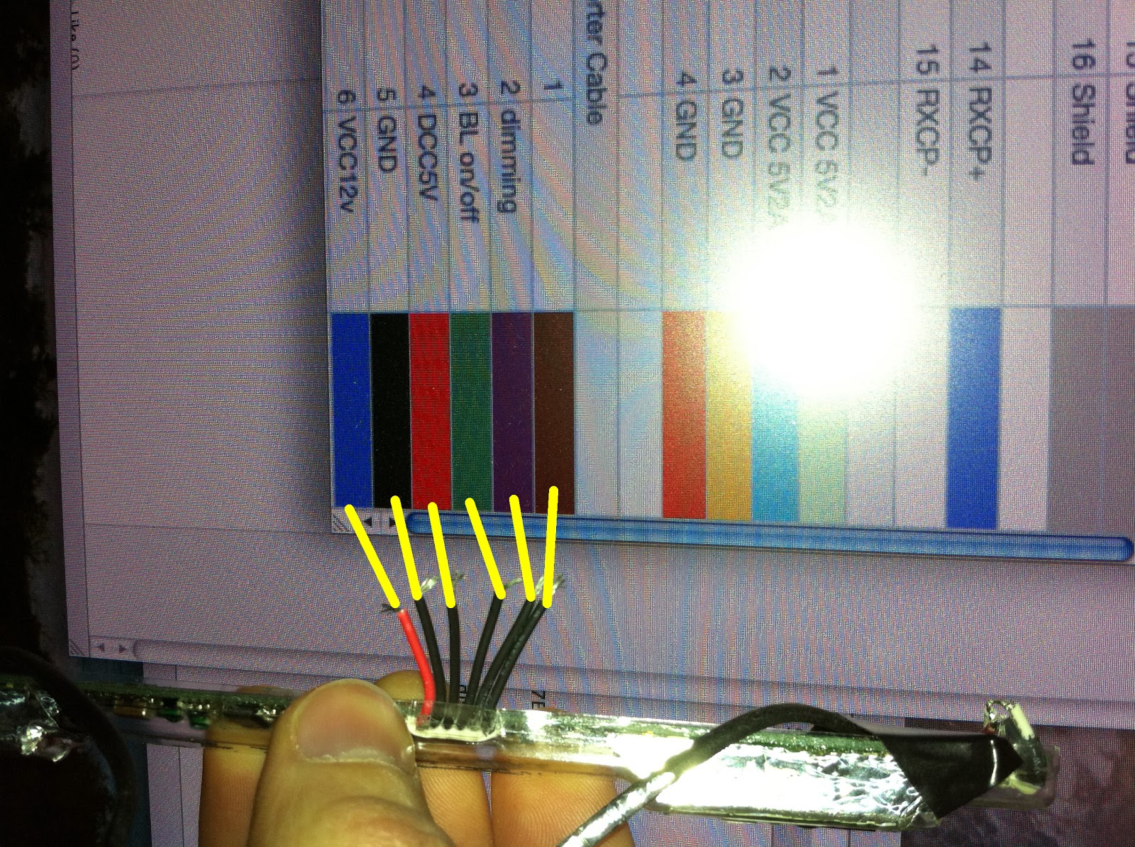
Pinout for a standard DVI cable.
Then I got to soldering. For the most part, everything went really smoothly. However, there were a few peculiar things.

I talked in my last post about the shield wires and how they correspond with the shield wires in the neck by not having any insulation on them.

Well, because this is only a 17" monitor, it only uses 3 of the 6 possible TDMS data triplets (pair of wires + shield). The first three coincide perfectly with the red, light blue & dark blue triplets.

JBerg's Pinout of the 17" iMac's screen
(note: There are two possible configurations.
This is mine. See JBerg's blog post for more info)
But the final triplet (marked on JBerg's pinout as RxC and on the generic pinout as TMDS Clock, presumably the same thing) uses the DVI Pins 22, 23, 24 which are correct as far as the pinouts go, but not from what is actually showing up on the connector.

On the connector, the shield wire (Pin 22) is not looking like the rest of the shield wires on the cable, even though it's being connected to a standard looking shield wire from the iMac's cable.

And then, pin 24 (the TMDS Clock -) wasn't even a wire on the cable. I had to pull another wire from the cable that wasn't being used and solder it to the connector. That was very strange.

So I finished the DVI cable, fallowing the pinouts above.

For the power cables (grey, green, blue purple, yellow & orange), I rigged up a detachable connection using the connector from the iMac's inverter and some little pins. I attached the three positives (purple, yellow & orange) and three grounds (grey, blue & green) to the connector end. On the other side, I jury rigged some pins and attached them to a 5V @ 1 amp AC wall adapter.

At this point, I had the DVI cable all made up and ready to go. I figured I'd give it a shot without bothering with the backlights, just to see if it worked. Of course, it didn't. Holding a flashlight up to the screen, there wasn't a hint of an image.

The only promising thing was the my MacBook's screen went blue for a second as it does when you connect it to an external monitor, but when it came back, it didn't give any hint of an external display... :-/

Time to call it a night though.

DVI Preparation

I ordered a DVI cable from Amazon in order to get the connector. I cut one of the ends off and tore it apart. The plastic used on these is pretty soft, so an x-acto knife was more then capable of doing the honors.

 Once I got the plastic off, the only thing holding the connector itself to the metal shielding was the crimped end where the wire comes out. At this point, the connector and accompanying wires can be pushed out the front with anything small enough to fit through the hole.

In order to make things (hopefully) a little easier on myself, I decided to leave the 1.5 inches of wire attached to the plug instead of soldering the cables from the monitor directly to it. So, I wen't ahead and cut off the pink shielding, separated and stripped the wires.

I found some interesting things when examining the cable ends. There are three pins (3, 11 & 19) that have two wires coming off of them. According to a DVI pinout (below) these are TMDS Data shielding wires. These are going to be extra important to pay attention to.


DVI Cable Pinout

Same pinout as above but indicating the groups that share wires.  
Why these shared wires don't have any insulation on them (neither in the iMac's cables nor this DVI cable), I have no idea. Making sure they aren't touching anything they're not supposed to be is also going to be tricky.

One final note: Incase I run into more video flicker issues (which apparently aren't crosstalk from the high voltage lines, but instead issues with the super thin wires in the iMac's black video cable (thanks JBerg)) I have the other end of the DVI cable with about three feet of cable which I can use to replace the cables in the neck entirely and solder directly to the connector behind the display of the iMac.

Wednesday, May 18, 2011

Starting Over

As much as I hate to say it, I'm calling it quits on this LCD path.

Where I'm coming from:
When I started this project more than a 18 months ago, nobody had gotten very far on this mod. I could only find one person who had gotten it to work with the native display, and it required the purchase of a $70 video driver that I wasn't sure was going to work. So I went my own rout and set about replacing the LCD panel itself and replacing the iMac's custom inverter to one in the base.

Unfortunately, extending and rearranging the backlight and video cables through the iMac's neck proved only problematic and I was never able to get it working. Whether the screen was flickering from cross talk due to the backlight high voltage lines or because of some unseen short in the 40+ new solder points in the video cable or twisted pairs getting separated, or any number of other issues, it just never worked.

Since I  started:
A few months ago, pinouts were made by fellow G4 modder JBerg of the native 17" iMac G4 LCD panel and an easy 1 to 1 correlation to a standard DVI plug. With this, there is no longer any need to completely gut and replace the display, use custom inverters, or ever take the screen off the base of the computer.  Having already invested so much time and money into my original plan, I was hoping to be able to stay the course and finish the job, but things don't always go the way you intend them to.

The Incident:
I was screwing around the other day, trying to get rid of the flickering image when I managed to short something out pretty bad and burn out my video driver. A nice puff of toxic smoke and the smell of burnt up silicone (and dreams) has pretty much convinced me it's time to go the DVI rout.

So this morning I ordered a new display assembly on eBay ($47, free shipping, not bad) so I'll be getting my DVI on as soon as that comes.


Quick Side Note: I've actually learned a lot from doing all this. I doing more mods with LCDs could be a lot of fun, so I'm glad I found this great eBay store that has everything you could ever want for LCD modding: http://stores.ebay.com/njytouch

Tuesday, May 17, 2011

Problems With Power


So I'm pretty sure I found the pinout for the native inverter, however, despite my best efforts, I wasn't able to get it working. To be fair, I couldn't be sure it ever did work. Part of the problem might have been my power supply. At first, I was hoping to use the iMac's power supply which is compact and custom made to fit inside the top of the iMac's dome. However, After a bunch of reseraching, I found there's not a whole lot of info online about the iMac G4's custom power supply. (Quick note on the pinout there, the BL on/off pin should require 5V via a 1K ohm resistor. Also, the dimming seemed to require between 3.3 and 0.8V to adjust the brightness of the display. I wasn't ever able to get that working however, and only had a 5V source to work with. I'm sure I'll be revisiting this one soon, though...) So here's what I found:

The iMac's power supply will only work if it's connected to a ground. In the iMac G4, only two lines actually go from the plug to the power supply. The ground wire deviates and screws into the metal internal shell of the computer. As far as I can tell, that's used to ground everything inside the machine, Including the power supply. Therefor, the power supply won't work unless it's installed in the computer the way it's meant to be and a ground cable is connected to the metal base.

But that's not all. Ther are four yellow and one blue lines coming out of the iMac G4 power supply (each with a corresponding ground wire). I'm not sure what the blue wire is, but the 4 yellows are 12V lines coming into the motherboard. (They actually read something like 14.8V)

Unfortunately, that's all you get from the power supply. If you want the 12V & 5V lines used for the CD & Hard drives, this cable has to be plugged into the motherboard and the computer has to be turned on. Whatever they do to drop the voltages, they do it on the iMac G4's motherboard. So as far as I have figured out so far, the G4's power supply wasn't going to work for me.

My solution was a DIY power supply. However, I'm not entirely sure my power source was up to the task. To make it, I used two AC wall adapters (5V & 12V), combining the negative wires together. This worked great for powering the video controller, but might not have been enough to power the inverter:


On the power supply for one of the monitors I have disassembled, It listed all the input and outputs for power. It looks like the inverter requires 12V @ 0.4 amps and 5.2V @ 3 amps. Unfortunately, I wasn't able to find a 5V AC adapter with more than 2.3 amps, so that may have been part of the problem....

Monday, May 9, 2011

Learning!

One of the benefits of incorporating this project into a school assignment, is I now have the full support and backing of my Digital Arts professor and, even more importantly, students. For example, today I learned some very interesting things. Like my static is more than likely caused by crosstalk between the high voltage lines and the video lines.

Also, One of my fellow classmates informed me that in the past when he was modifying LCDs, he noticed that if you increase the length of those high voltage lines, it tends to burn out the inverter really quickly. SO, back to the drawing board.

I figure it's not too late to use the custom inverter that came with the iMac. The challenge with it is bypassing the inverter on the LCD power supply and wiring the iMac's inverter to it.

Sunday, May 8, 2011

Stalemate

So it turns out the high pitched squealing sound is the same sound I heard before. I can change the pitch of the sound by moving the backlight wires(especially the pink high voltage lines) around. So that aside, I wanted to figure out a cleaner way to bring the video into the LCD panel. By simply swapping out the pins into the new connector head, many of the new pins were sliding out very easily and I could never be sure if it was making a good connection to the LCD Panel circuit board.

So, I had this ribbon cable that came off my first monitor I decided to use. The connector on one end fits perfectly into the LCD Panel circuit board, so it was just a matter of soldering the video cable ends to the other end. 

I started by using an x-acto knife to split the ends of the ribbon so I can separate each of the wires for soldering. 

With the ribbon prepared, I pulled all the pins out of the old connector and began soldering and shrink-tubing each one. 

After I got them all soldered up (only about 2 hours worth of work), I took it all back, plugged it in, and... you guessed it. Still not quite working. Although, this time, something slightly different is going on. It's showing a pure white screen most the time, but if I pinch the video cable together in just the right way right near the solder joints I just made, I can get the video to flicker on and off... Progress, right?

Tuesday, May 3, 2011

Neck Surgery Pt. 2

Finally got the neck back together. It was a lot harder than I remember it being...  Anyway, with the backlight wires in the neck, I spent today soldering on plugs and basically neatening everything up in hopes that would fix my video issues.

Feeding the cables through these white tupes is pretty easy, assuming you haven't soldered the little clips on the ends first. Make sure you wait until cables are through the white tubes before you go soldering ends on to them. It will make your life easier.

So, I got everything set back up, fired it up, and it almost kinda worked. At first a proper image blinked on and off a couple of time before going completely black. I didn't have time to determine if it was the backlights flashing or the video, but once it stopped, the backlights weren't on. Of course, I had to try it again, so I shut off power to the monitor and booted it back up.

This time, I got a black video BUT the backlights were on, accompanied by a high-pitched squealing similar to the one I got a while back. Not wanting to press my luck, I decided to call it a night. If this has anything to do with the cables being coiled/twisted like it did before, I'm going to be pissed. I do not feel like taking that neck apart again. If I accidentally pop it apart again, I'm not sure I'm going to be able to pop it back together again without doing some damage to it...


Monday, May 2, 2011

Neck Surgery

I managed to get the screen working decently well (turns out I had the plug coming out of the video card backwards). The picture was good, affected only by some slight red static, so I decided to go ahead and put the backlight cables into the neck.

In order to make room, I decided to remove the group of cables that took power to the old inverter, seeing as how they weren't in use any more (except for 1 which I spliced into to carry an extra video signal wire). Unfortunately, inside the neck, this group of wires is heat-shrunk to the set of wires carrying the sleep/wake LED and microphone, both of which I would like to use later, so they'll have to be unwrapped all the way.

The heat shrink tubing goes all the way into the pivot points, so you'll have to pull the cords farther into the neck by about an inch to get it all off.

For threading the new wires through, I found it easiest to bundle them into small groups rather than trying to pull them all through at once. I pushed a spare piece of solid core wire through the top of the neck and used it to pull the 2 groups through one at a time, starting with the biggest.

I found the taped part went around the tight corners the easiest the smaller it was, so I tightly wrapped the group with the solid core wire with as little tape as possible, doing my best to keep it in a concise length.

I then spent another half an hour unsuccessfully trying to pop the neck back together, but it just wasn't having it. Oh well, more to come in the coming day(s). 

Guess Who's Back, Back Again.

Most people don't drop projects like this and then come back 1.5 years later to finish them. But I'm not most people, and so, I am back to finish what I started. And this time, it's going to work. Why? Because it has to. I've managed to work this into a school assignment, which is due June 1 at 8:00am. That's 29 days and 15 hours. Yikes.

A million thanks to JBerg, once again, you were absolutely right about my backlight flickering issues. Instead of running the backlight cables through the existing wiring, I got the real stuff (see JBerg's comments on the previous post), and IT WORKED! Well, sorta. The backlights now turn on, but the image was just white. No video signal was coming through.

I messed around with the cable coming into the LCD panel and managed to get some flickering images (backlight remained on) so I unplugged everything and made sure all the little pins were properly secured. However, when I went to plug everything back in again, I got nothing but that white screen again. Now I'm a little stuck again. I cannot figure out why I no longer get anything when I wiggle the cables. I made sure they were all pushed in, cleaned the contacts with a Q-tip dipped in windex, but it's acting like there's nothing getting through...